Reactor Theory and Practice
Other Considerations
In many teaching exercises it is only desired that students observe the properties of biofilms in a subjective manner with no intent to make quantitative measurements of what is being observed. On the other hand, many studies students may wish to carry out will require quantatitive physical and numerical measurement of biofilm growth, increasing cell number, resistance to microbicides, biofilm thickness and mass. Protocols enabling students to conduct each of these measurements are also found in the exercise collection.
Measuring the thickness of biofilms in a non-destructive manner is easily accomplished according to instructions given in Exercise 13 Measurement of Biofilm Thickness. The measurement requires only a simple modification of a standard student microscope, which permits measurement of the vertical movement of the objective lens.
Harvesting and Dispersing of Cells from Biofilms
Because biofilm cells are attached to a substratum and contained within a slimy matrix, their enumeration by plate counting requires techniques somewhat different than those used for planktonic populations. The cells must first be harvesting from the surface and dispersed into suspensions of individual cells. They can then be treated in a manner similar to planktonic cell populations by serial dilution and plate counting. The procedures for harvesting, dispersing and enumerating biofilm cells are found in Exercises 10 and 11 (Harvesting and Dispersing of Cells from Biofilms (10 Standard Method) and (11 Alternate Method) and Exercise 8 - Drop Plate Method for Counting Biofilm Cells.

Measurement of Biofilm Mass
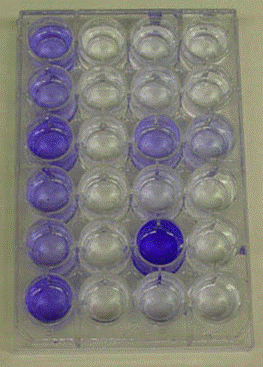
Sometimes measurement of biofilm mass is a sufficient quantitative measurement. Exercise 6 - Colorimetric Measurement of Biofilm Density describes a method for measuring the relative mass of biofilm growing in a 24 well microtitre plate. The biofilm is stained with crystal violet dye, then washed to remove unbound dye. The bound CV is then eluted with alcohol. The amount of crystal violet dye recovered, measured colorimetrically, is proportional to the mass of biofilm in the well.
Nutritional considerations
Many biofilms grow in conditions that are oligotrophic, that is low in nutrient concentration. In order to mimic these conditions, nutrient levels must be chosen that are appropriate for the environment in question. Biofilms will grow, albeit slowly, in tap water with no added nutrient at all, an oligotrophic environment indeed.
One of the more commonly used media for culturing biofilms is R2A medium. R2A medium is a low nutrient medium developed for the enumeration by plate count of bacteria from treated potable water. This medium has been shown to favor the growth of stressed organisms such as those grown at low nutrient concentrations or exposed to chlorine and comes closer to modeling the natural conditions in which biofilms grow than richer media such as Plate Count or Brain Heart Infusion Agar.
DifcoTM R2A Agar
Approximate Formula* Per Liter
Yeast Extract .....................................................................0.5 g
Proteose Peptone No. 3 ..................................................0.5 g
Casamino Acids ................................................................0.5 g
Dextrose .............................................................................0.5 g
Soluble Starch ...................................................................0.5 g
Sodium Pyruvate ..............................................................0.3 g
Dipotassium Phosphate .................................................0.3 g
MagnesiumSulfate...........................................................0.05 g
Agar ....................................................................................15.0 g
*Adjusted and/or supplemented as required to meet performance criteria.
Another medium that has been frequently used in biofim reactor studies is M9 Minimal Medium the recipe for which follows (from theLabRat.com):
M9 Minimal Media Recipe (1000 ml)
- Make M9 salts
- To make M9 Salts aliquot 800ml H2O and add
- 64g Na2HPO4-7H2O
- 15g KH2PO4
- 2.5g NaCl
- 5.0g NH4Cl
- Stir until dissolved
- Adjust to 1000ml with distilled H2O
- Sterilize by autoclaving
- Measure ~700ml of distilled H2O (sterile)
- Add 200ml of M9 salts
- Add 2ml of 1M MgSO4 (sterile)
- Add 20 ml of 20% glucose (or other carbon source)
- Add 100ul of 1M CaCl2 (sterile)
- Adjust to 1000ml with distilled H2O
Students have also had good results growing biofilms in 1/10 or even 1/40 Tryptic Soy Broth or Tryptic Soy Agar. Presumably other media at reduced concentrations would also serve and determining the optimum concentrations for any particular system would, in it self, be a worthy student project.
Shear forces or hydrodynamic stress
Shear is the force applied to a biofilm by the flow of water or medium, which tends to remove the biofilm by erosion or sloughing. The amount of shear placed on a biofilm during growth has a profound effect on the architecture of the mature community. For example, “a Pseudomonas aeruginosa biofilm formed in a reactor with high shear is denser and more tightly adhered to the surface as opposed to a P. fluorescens biofilm formed in a reactor under low shear, which is fluffy3.” Four typical environments, all experienced in nature by natural biofilms can be modeled in reactors of various sorts in the laboratory, high shear with turbulent flow, moderate shear, low shear and no shear3. Both the Stirred Batch reactor (Exercise 1 and the Continuous Flow Stirred Reactor can be operated to produce High shear, turbulent flow or moderate flow depending on the rate of stirring. The Static Glass Coupon Reactor (Exercise 13) is an example of a no flow reactor and the Drip Flow Reactor (Exercise 20) produces a low shear environment.
Exercise |
Reactor Type |
Shear |
1 |
Batch reactor |
Static to high shear, no flow to turbulent flow |
3 |
Continuous Flow Stirred Reactor |
Low to high shear, laminar to turbulent flow |
4 |
Flow cell Plug flow reactor |
Low to high shear, laminar to turbulent flow |
14 |
Biobarrier column, Plug flow reactor through a porous matrix |
Low to moderate shear, turbulent flow |
13 |
Static glass coupon reactor |
No shear |
20 |
Drip flow reactor, open plug flow reactor |
Low shear, laminar flow |
