A substantially updated version of the hypertextbook is available here. Please migrate to that version. This one will eventually disappear.
Building and Using a Flow Cell Biofilm Reactor
Introduction:
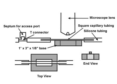
A flow cell is a device that permits the microscopic observation of the initiation and growth of a biofilm in real time. It is constructed simply from a piece of square capillary tubing mounted on a base. The flow cell is placed on the stage of the microscope and a source of microorganisms and nutrient is permitted to pass through the tube. Observation over time will permit you to follow the various stages of biofilm development (See Figure 1).

In this exercise you will construct one type of flow cell and use it to observe biofilms forming in real time under your microscope. You will observe attachment, growth and division of the cells of the biofilm, the production of extracellular polymeric substances (EPS), and possibly the aggregation of other materials to the growing biofilm. You should carefully examine the biofilm to observe its structure and distribution, the presence of any open water channels in the mature biofilm, the presence of towers and “mushroom-shaped” microcolonies, streamers and any evidence of biofilm viscoelasticity.
Instructions:
There are four components of a basic flow cell reactor system these are:
- the nutrient supply
- an access port
- the flow cell
- the waste disposal container
Your instructor will advise you on the source of microorganisms you will use and the necessary nutrients. She will also indicate how you will dispose of waste materials if necessary. In this section you will construct a flow cell and an access port by which you can add materials to the system while it is in operation without dismantling the flow cell.
Supplies Needed:
For the Flow Cell
According to your teacher’s instruction, use or construct one of these bases.
|
Quantity |
Description |
| 1 | 1 X 3 X 1/8 inch acrylic base OR; |
| 7" | 1/4 x 1/4 inch clear acrylic rod stock OR; |
| 1 | 2.5-3" metal washer |
OR Use |
|
| 1 | 4" section of square capillary tubing, 2mm I.D. |
| 1 | super glue |
For the Access Port
|
Quantity |
Description |
| 1 | T-barbed fitting connector |
| 1 | rubber sleeve stopper |
| 1 | polycarbonate tensioning tool |
| 1 | 4" strap or cable tie |
For General Assembly and Operation
|
Quantity |
Description |
| 1 | silicone tubing, cut into 3 pieces |
| 1 | Peristaltic Pump Fisherbrand, Variable Flow |
| As Necessary | Gloves |
The Flow Cell
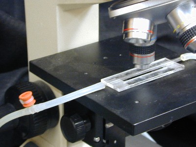
The flow cell consists of a base made of plastic or metal and a square glass tube of optical quality glass through which microorganisms and nutrient will be pumped. This device can be placed on the stage of your microscope so that you can observe the development of a biofilm in real time (see Figure 4). For this flow cell you will be using 2 mm inside diameter tubing. This is fairly b and not easily broken. Its wall diameter is thicker than the working distance of a typical oil immersion lens, so in observing the biofilm we will use only the 10 X or High Dry lens.
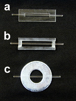
Your teacher will instruct you which type of flow cell base you will be using or building (see Figure 5a, b and c).
Type a:
Select one of the prefabricated acrylic bases and one 4” piece of square capillary tubing. Carefully apply a small amount of Super Glue to each end of the base and place the tube on it so that the tube runs the length of the base with its center aligned with the center of the slot. Permit the Super Glue to set.
Caution: Cyano-acrylic cements like Super Glue and can bind fingers and skin in seconds. Use great care not to get any of the glue on your hands.
First Aid: Should binding to fingers or skin occur, immerse the affected area in warm soapy water and gently peel or roll the skin back and forth until the affected parts separate. Repeated washes in warm soapy water will permit you to peel off adhering super glue. In the event of cyanoacrylic contact with the eyes, seek medical assistance immediately.
Type b:
If preformed bases are not available you will have to make one. Using the fine toothed hobby knife, carefully cut two 3” pieces of the 1/4 “ thick acrylic rod stock. Also cut 2 x 1/2 inch pieces of the rod stock. Now assemble the four pieces into a 1” x 3” rectangular frame, and fasten thee parts together with Super Glue. Permit the frame to harden (Figure 5b).
Caution: Wear goggles while cutting the tubing, as it can shatter. Use all appropriate precautions when using cyano-acrylic cement. It binds to fingers as well as to plastic and glass.
Secure the 4” piece of square glass capillary tubing to the frame by applying some of the glue at each end of the frame and placing the tubing into the cement. (See the caution about cyano-acrylic cement above.)
Type c:
A third and very simple base can be made from a large metal washer (2.5 inches in diameter). The square tubing is simply glued to the top of the washer through its diameter (See Figure 5c).
The Access Port
It is often desirable to be able to introduce or remove
materials into or out of the system without compromising the
sterility of the flow cell. An access port placed upstream
and/or downstream from the flow cell will meet this need.
Place the narrow end of a rubber sleeve stopper onto the stem
portion of a plastic T-connector (Figure 6).
Once this is inserted into the line between the nutrient
source and the flow cell, materials such as nutrients, other
organisms, antimicrobics and dyes can be inserted into the
system by clamping off the medium flow (up stream from the
access port) and injecting the desired material through the
access port and into the T-connector. It is recommended that
the septum be disinfected prior to and after injecting any
materials. Clamping above the port ensures that the material
flows in the direction of the flow cell.
Note: Ask your instructor about the proper disposal of needles
and sharpes.
Note: For a more secure fit, the cup of the
sleeve stopper can be inverted back over the stem of the
T-connector and this can be held in place with a 4” cable
tie tightened with a tensioning tool. When tightening the strap
around the base hold the sleeve tight to the T-connector so
that the cable tie wraps around the stem below the barb.

Assembly and Use
If desired, all of the components of the apparatus may be autoclaved except the flow cell itself. The flow cell can be disinfected with alcohol.
It is a good idea to place the flow cell in a pan that can hold the entire volume of the culture or medium supply in the event of a leakage accident.
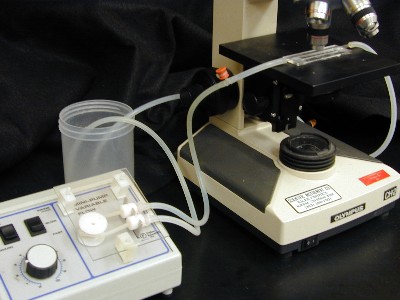
The cell may be set up in a recirculating or flow
through pattern. Your teacher will instruct you which
system to use.
A recirculating system is the easier system to set up.
In this pattern a plastic tube from a culture (e.g. a hay
infusion) is passed through the peristaltic pump. The access
port is attached to the outflow from the pump and then to the
flow cell. The effluent from the flow cell is directed back
into the culture. In this pattern no waste disposal container
is necessary. An aquarium, a known culture, a pond water
sample, or a sample from any natural water supply may be
substituted for the hay infusion. Each will produce its unique
biofilm in the cell.
A flow through system requires a source of inoculum, a
medium supply and a waste container. The sterile access port
and flow cell are connected to the medium supply and the medium
flow is adjusted to the desired flow rate by adjustment of the
peristaltic pump. After the system is filled with medium, the
pump is turned off and the tube between the pump and the access
port is clamped off. The culture of interest is injected into
the access port and the system is allowed to incubate for a
period of time (commonly over night), so the attachment of
cells to the flow cell will occur. At this point the clamp is
removed and the pump started so that the newly attached cells
will receive nutrient.
If desired, all of the components of the apparatus may be
autoclaved except the flow cell itself. The flow cell can be
disinfected with alcohol.
Note: Biofilms typically prosper at low nutrient
concentrations, so 1/10 nutrient broth, TSB or LB broth is
likely to produce a better effect than full strength
medium.
Follow-up Activities
- Place two flow cells in tandem each on its own microscope. Feed the two flow cells from a heavily overgrown aquarium with lots of algae and cyanobacteria. Cover one flow cell with aluminum foil to exclude light and illuminate the other. The illuminated flow cell should exhibit autotrophic organisms while the dark one should be exclusively heterotrophic.
- Once a biofilm is established, introduce a disinfectant, detergent or antibiotic through the access port and observe the results.
- Introduce a stain like carbol fuchsin or methylene blue through the access port and observe the result. Note this may damage the biofilm.
- Measure the length of “streamers” with an ocular micrometer and then increase the flow rate with the pump and measure the length of the streamer again. Plot streamer length as a function of flow rate. Now slow the flow rate while measuring “streamer” length. What happens to the length of the streamer as flow rate is increased and decreased? This simple procedure exhibits the viscoelasticity of biofilm extra polymeric substances (EPS).
References:
Detachment, surface migration, and other dynamic behavior in bacterial biofilms revealed by digital time-lapse imagingStoodley P, Hall-Stoodley L, Lappin-Scott HM
Methods in Enzymology, (2001) 337:306-319
Microscopy flowcells: Perfusion chambers for real-time study of biofilms
Palmer RJ Jr
Methods in Enzymology, (1999) 310:160-166
Acknowledgments:
This exercise was suggested by Dr. Paul Stoodley
Educational Program Curricula and Teaching Resources
Supported in part by the Waksman Foundation for MicrobiologyDeveloped in collaboration with Dr. John Lennox, Education Editor, Penn State Altoona
©2002-2006 Center for Biofilm Engineering, http://www.biofilms.montana.edu